CONCRETE FLOATING BOAT DOCKS

Concrete
Floating Boat Docks

Pontoons & Concrete Floating Boat Docks


Long-lasting marina dock system

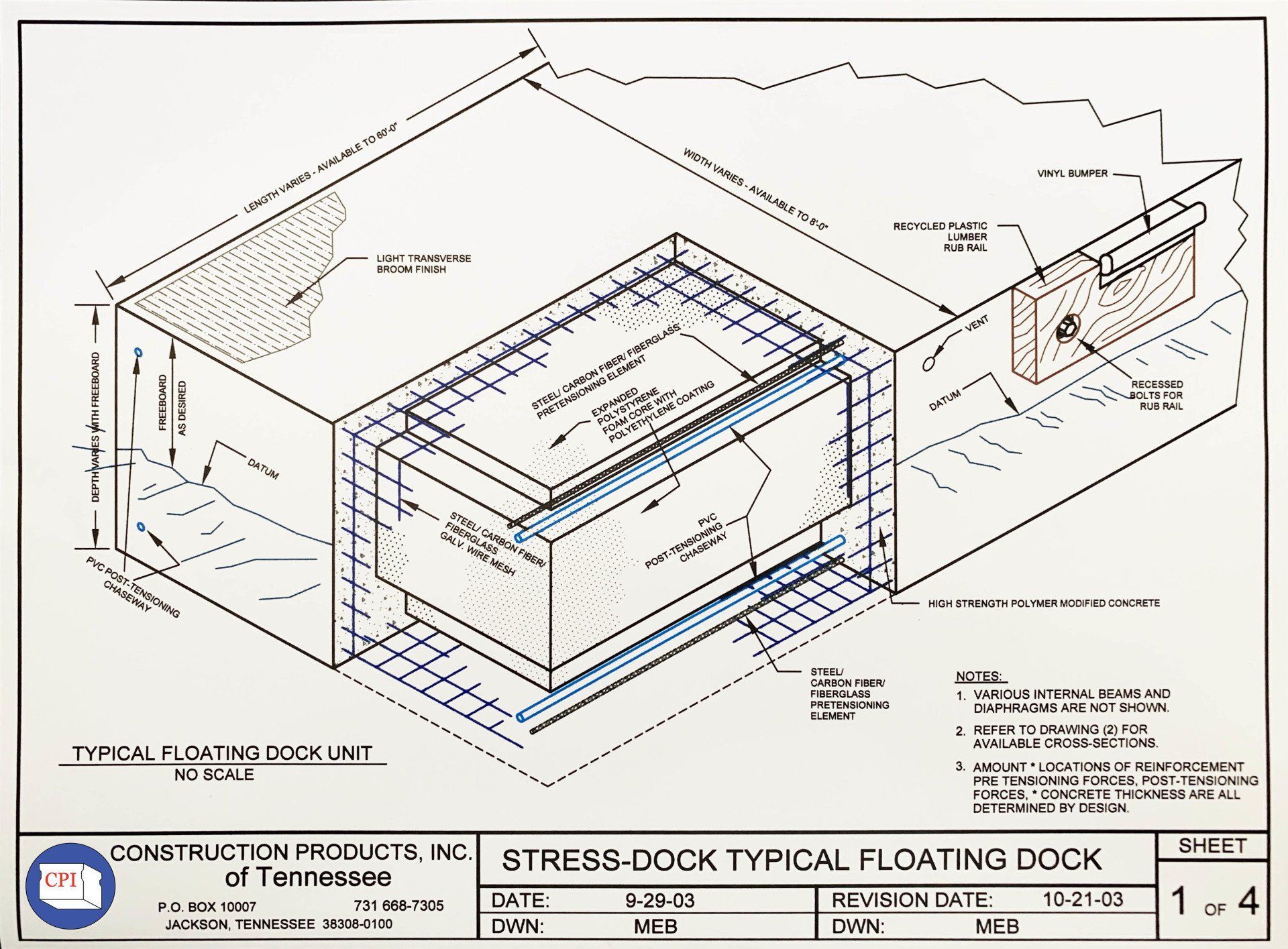
Our patented Stress-Dock™ is a dock with the comprehensive strength of concrete and the tensile strength of steel. The precast-prestressed floating dock systems are low maintenance, will last for decades, and provide a clean, uniform appearance to any marina.

Concrete, being impervious to attack from ultraviolet light, petroleum products and hungry animals, is long lasting. Those three items wreak havoc on the floating foam of some marina systems. CPI’s floating concrete boat docks last for an indeterminate length of time. For example, Construction Products installed the still-functioning docks in Baltimore Harbor in 1975.

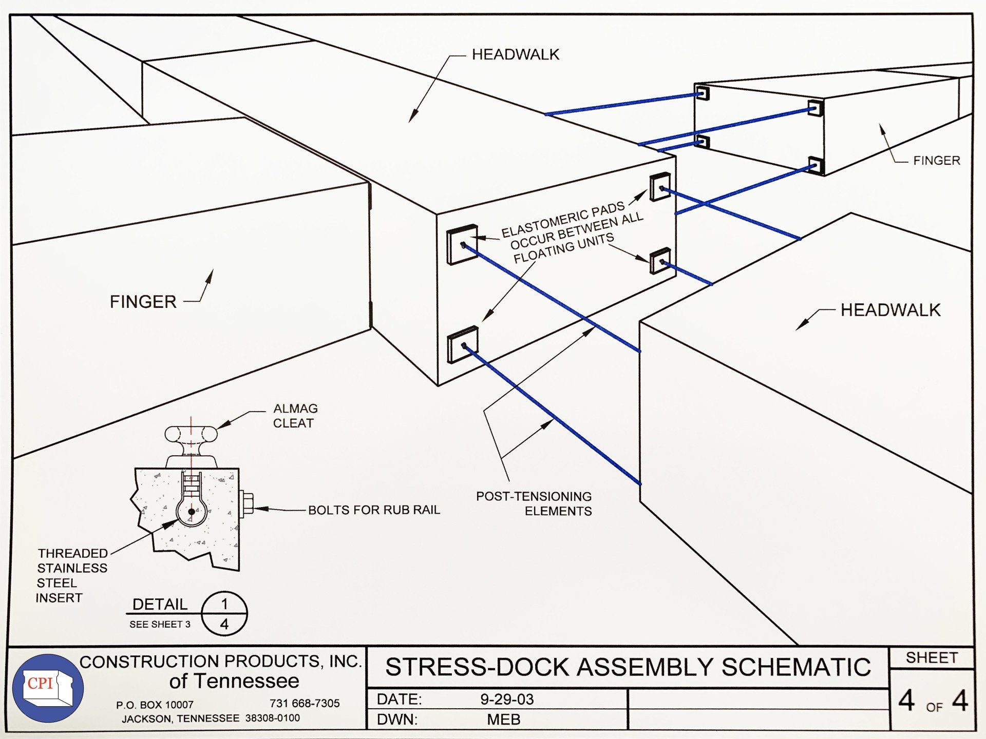
The docks are prestressed and reinforced with a combination of galvanized steel and reinforcing fabric. A system of pipes and cables allow the floating docks to be linked together. Construction Products customizes the docks differently for fresh and salt water applications. Installation can be provided or CPI can work with the marina’s contractor.

Construction Products works in conjunction with architects and engineers in marina design. The custom-built docking system is shipped in sections for on-site assembly.

Patented Stress-Dock™ System

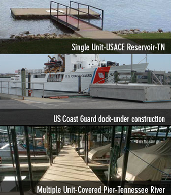
Wade Thomson developed a patented concrete floating boat dock trademarked as Stress-Dock™ in 1973, and we have been incorporating improvements ever since. This successful docking system can be seen at:
  • Baltimore Inner Harbor Marina - Baltimore, Maryland
  • U.S. Corps of Engineers – Cumberland River locations
  • Riverside Park - Nashville, Tennessee
  • Titans' Football LP Field Stadium Mooring Facility - Nashville, Tennessee
  • Kentucky State Parks
  • Tennessee State Parks

Stress-Dock™ Advantages

The newest patent version of the Stress-Dock™ incorporates many improvements that create a corrosion-resistant dock system by utilizing engineered fabrics and fibers for a rust-free structure.

Advantages of our patented design include:
  • Strong & Durable
  • Lifespan of 25 years or more
  • Corrosion Resistant
  • Rust-free Engineered Fabrics & Fibers
  • Easy Installation
  • Perfect for Harsh Environmental Conditions
  • Low Maintenance

Floating Piers built with the Stress-Dock™ System

The drop-down menu below contains information about our process, as is found in our typical Floating Pier / Boat Dock construction agreement.
  • Design

    Floating pier units shall be designed in accordance with ASCE Report No. 50, “Small Craft Harbors” 1969 or current edition.


    Freeboard under full dead load shall be a minimum of 18” from top of deck to water level. Freeboard under combined full dead load and live load shall not be less than 16”. Design live load shall be not less than 30 pounds per square foot of surface area. 


    All connections for finger piers and main piers shall safely withstand a wind load of 15 pounds per square foot against the average profile height of the berthed vessels. In addition, the piers shall resist and impact load of an approaching vessel equivalent to a thrust of 5000 pounds at the end of any dock, applied perpendicular to the side of the end of the finger. 


    The floating pier units shall be precast-prestressed concrete encasing polystyrene. The concrete for a three or four foot wide unit shall have a minimum deck thickness of 3”, minimum side thickness 2”, and bottom thickness of 1 ½“ or as directed by the engineer.


    Flotation Integrity - Flotation units shall be designed to maintain their desired buoyancy and freeboard even if structurally damaged (i.e., broken in half). Connections of flotation units shall be so designed that the floating pier acts as a unit. One unit does not deflect without adjacent units deflecting and no vertical slip will occur between units when deflecting. A rigid system is required which will neither rach nor twist unreasonably in torsion.

  • Materials: Expanded Polystyrene Foam

    Virgin expanded polystyrene foam with minimum density of 1#/cubic foot shall be used for the inner core of all floating dock components. Expanded polystyrene foam shall be expanded Dylite or approved equal. Representative samples shall be taken from each day’s foam production and tested for water absorption. Water absorption is excess of 2% by volume, when submerged for a period of 24 hours, shall be cause for rejection of the foam. Accurate records of water absorption tests shall be kept at the manufacturing facility. Copies of these records shall be furnished to the Architect/Engineer.

  • Materials: Strand

    (1). Pe-stressing Strand


    All strands used for pre-stranding shall be ⅜” or ½” diameter galvanized in accordance with ASTM A416 or stainless steel as directed by the engineer.


    (2). Post-Tensioning Strand


    (a) Tendons:

    All strands used for post-tensioning shall be ⅜” diameter Type 270K, galvanized or, thermally bonded, cross-linked polymer coated in accordance with ASTM A416. All post-tensioning strands shall be tensioned to a minimum of 8000#. Elongation measurements shall be taken during the tensioning process and checked for conformity with the strand properties. Deviation in excess of five percent shall be reported to the Architect/Engineer and may be cause for rejection. The complete tendons for post-tensioning shall be coiled and fastened on shipping racks so constructed that each tendon is protected from damage during the transit and storage at the job site. All tendons shall be protected from oxidation or other forms of corrosion prior to placing, and shall be kept free of deleterious substances. Stainless steel strands may be required by the plans or as directed by the engineer. Raceways may be injected with a hydrophilic compound. 


    (b) Tendon Anchorages:

    When shown on the approved shop drawings, anchorages shall be constructed to develop the full ultimate strength of the tendons, without slippage, distortion or other changes that will permit loss of stress. 


    Anchorages shall be detailed to transfer the post-tensioning forces to the concrete without creating bending moments in the tendons. Anchorage hardware shall be clean and free of deleterious substances and shall be constructed as shown on the approved shop drawings. Neither the tendons nor the anchorages shall be nicked, bent, or damaged in any way. Ductwork details at the anchorages shall be shown on the shop drawings. Stainless steel chucks shall be used in all cases.

  • Materials: Joints - Neoprene Pads

    All Neoprene pads shall be ½” (or as shown on the shop drawings) thick 79 durometer hardness. Care shall be taken not to allow the in-place neoprene to extend to the top or side-edge of the floating pier components. The neoprene should be held back from all free edges a minimum of ½:” All neoprene pads shall be checked for correct positioning just prior to the installation of the adjoining units.

  • Materials: Rub Rails

    Wood rub rails shall be a minimum of 2” X 6” or otherwise of the size and configuration indicated on the shop drawings. Lumber shall be #1 or better Southern Yellow Pine as per the standard grading rules of the Southern Pine Inspection Bureau. Lumber shall be Cellon pressure treated with 0.6lbs./cu. ft of dry pentachlorophenol salts according to Federal Specifications TT-W-572 or approved equal. All lumber shall be S4S (surfaced four sides). Wood rub rails shall be affixed to the sides of the floating dock components using stainless steel bolts and washers recessed in center sunk holes on 24” centers. Wood to wood connections shall be accomplished using aluminum nails on 2” centers. Recycled plastics rub rails may be used in place of wood.

  • Materials: Pile Guides

    All pile guides shall be fabricated in accordance with the details on the shop drawings from steel or aluminum conforming to ASTM A-36 (steal) and shall be hot-dipped galvanized after fabrication with a minimum coating of 2 ounces per square foot.

  • Materials: Bumper Strips

    Bumper strips for floating piers shall be white PVC type mounted on wood rub rails. Bumper strips shall be Vinylex deluxe white CDS-3 ½” or approved equal. 


    Bumper strips shall be attached to the wood rubs rails by 1 ¼” aluminum roofing nails at not greater than 5” centers.


    Bumper strips shall be manufactured by Vinyles Corporation, 2636 Byington-Solway Road, Knoxville, TN 37931, or approved equal.

  • Materials: Mooring Cleats

    All mooring cleats shall be 10” cast units from an approved source. Cleats shall be installed at the locations shown on the shop drawings. Cleats shall be affixed to the deck surface using approved neoprene expansion shields or approved equal. Bolts, nuts, and washers shall be stainless steel.

  • Materials: Access Ramps

    (1) Access ramps other than shown on drawings shall be designed for vertical live and dead load plus 100% of the vertical live load for impact. All bolts shall be stainless steel.


    (2) Wheel Bearings shall meet the following requirements:


    (a) Bearings shall be heavy-duty and designed for continuous movement.


    (b) Bearings shall be designed to be non-seizing due to rust and ice.


    (c) Non-delrin Bearing shall be fabricated with either an oil-impregnated bushing or with standard pressure-type grease fittings. Grease shall be water-resistant type as recommended by the access ramp manufacturer.


    Access ramps shall be connected to the access ramp anchors by means of a hinge and pivot.


    Walkway surface shall possess adequate non-slip characteristics at a slope of 1” vertical and 12” horizontal maximum. Access ramps shall be provided with handrails on both sides per ADA.


    Buoyancy: Flotation carrying the access ramp shall be of sufficient volume to support the combined pier and access ramp dead loads.


    Handrails shall be as shown on the drawings, and steel materials shall be hot -dipped galvanized after fabrication.


    All metals shall be A36 steel or aluminum unless otherwise specified and painted with a paint system as approved by the Architect/Engineer. 

  • Materials: Bolts, Nuts, Washers, Inserts

    All bolts, nuts, and washers shall be as indicated on the shop drawings, or if not so indicated, shall be of the sized, shapes, and lengths sufficient for their intended uses and shall be stainless steel after fabrication. All bolts shall conform to ASTM A307, or as indicated on the shop drawings. Protection from galvanic action of dissimilar metals shall be provided.

  • Materials: Vermin Proof

    Flotation units shall be so designed that the top, bottom, and sides of the units are protected with a maintenance-free material for protection against vermin.

  • Materials: Resistance to Petroleum and Detergents

    Flotation units shall be so designed and constructed to prevent deterioration from petroleum and detergents. Any material used inside flotation units that is susceptible to attack from these agents shall be fully enclosed with an approved covering to prevent deterioration.

  • Materials: Connections

    Shall be so designed that units can be disconnected and moved. Connections shall be so designed that bracing shall not be required to extend underwater between fingers in the area of the slips. All ferrous materials, whether classified connections of structural members, shall be hot-dipped galvanized 2 oz. minimum coating.

  • Materials: Deck Materials

    Walkway and finger top surfaces shall be concrete construction and shall possess adequate non-slip characteristics. The contractor shall furnish a written one-year material and workmanship warranty for repair and replacement of deck materials used if found faulty during this period. Epoxy based non-skid coatings are optional.

  • Materials: Fabrication

    Floating pier units shall be completely prefabricated by the pier manufacturer at his plant and delivered ready for flotation at the site. Marine accessories such as cleats, fenders, etc., shall be applied in the field.

  • Materials: Shoe Drawings

    Contractor shall submit complete drawings with calculations for final approval, showing shop details of piers, pier connections, fastening to anchorage, piping and conduit location and attachment, etc., to the Architect/Engineer before fabrication. Drawings and calculations shall be sealed by registered Professional Engineer.

  • Materials: Installation

    Pier units shall be carefully unloaded and kept in orderly piles or stacks until floated in the water. None but competent craftsmen shall be employed to float and anchor the piers. Workmanship shall be first class throughout.

  • Materials: Mantainability

    Wherever possible, parts shall be mounted so that they can be removed and replaced without interference from, injury to, or removal of other parts or utilities.

  • Materials: Manufacturer’s Experience and Supervision

    The manufacturer of the modular, pre-stressed concrete floating pier units shall have evidence of satisfactory experience for a minimum of the last five years in design, manufacturing, and installation of the floating system of which he proposes to bid and as specified herein.


    To demonstrate his competence, the manufacturer may be required to submit to the Architect/Engineer a listing of a minimum of three projects for which the has furnished floating modules of the type herein specified. 


    To assure that assembly and installation of the floating modular units is performed in accordance with the manufacturer’s recommendations, the manufacturer shall provide a qualified representative at the job site during the assembly, installation, and anchorage of the floating modular units.

  • Share by: